STM32 Automotive Headlight Controller
A multi-revision STM32 controller for independent operation of a Mazda Miata's 12 V pop-up headlight motors, combining relay control, embedded firmware, automotive power protection, and a custom KiCad PCB.
Overview
This project started as a way to give a Mazda Miata's pop-up headlights more expressive motion while keeping the control system electrically safe and predictable. The controller can operate the left and right headlight motors independently and execute timed motions such as individual winks, both-headlight motions, and a partial-open “sleepy eyes” position.
I first validated the behavior on an STM32F446RE Nucleo with a four-channel active-low relay module, then moved the design toward a dedicated automotive PCB with on-board power regulation, relay control, protection, connectors, and debugging access.
Prototype Architecture
The working prototype uses four relay-control outputs: left motor up, left motor down, right motor up, and right motor down. A single momentary pushbutton provides the user interface, and the firmware interprets click count and hold time to select different headlight actions.
| Prototype signal | STM32 Nucleo pin | Function |
|---|---|---|
| LEFT_UP | D2 | Raise left headlight motor |
| LEFT_DOWN | D3 | Lower left headlight motor |
| RIGHT_UP | D4 | Raise right headlight motor |
| RIGHT_DOWN | D5 | Lower right headlight motor |
| BUTTON | D8 | Momentary input using internal pull-up |
User Controls
The controller uses one button rather than several dedicated switches. The firmware detects single, double, and triple clicks as well as two hold durations. That keeps the in-car interface simple while still allowing several behaviors.
| Input | Action |
|---|---|
| 1 click | Left headlight wink |
| 2 clicks | Right headlight wink |
| 3 clicks | Double wink / both headlights |
| Long hold | Sleepy-eyes partial opening |
| Very long hold | Close / off command |
Firmware Timing
Headlight motion is time-based, so the firmware uses explicit timing constants rather than leaving a relay energized indefinitely. The same timing layer is also used to separate opposing commands and to recognize button gestures.
| Parameter | Value |
|---|---|
| Relay dead time | 200 ms |
| Wink up | 900 ms |
| Wink down | 900 ms |
| Full open | 900 ms |
| Full close | 900 ms |
| Sleepy-eye opening | 220 ms |
| Between actions | 900 ms |
| Maximum relay-on time | 1200 ms |
| Button debounce | 40 ms |
| Multi-click window | 500 ms |
| Long press | 900 ms |
| Very long press | 2500 ms |
Safety Logic
A key firmware requirement is preventing the same motor from receiving UP and DOWN commands at the same time. The output layer blocks conflicting commands and inserts a 200 ms dead time before reversing direction. A maximum relay-on timer also limits how long a command can remain active.
These checks were built into the control layer rather than relying on the user to avoid unsafe command combinations. The prototype also uses active-low relay outputs, so the firmware explicitly controls the inactive state of every channel.
Custom PCB / Rev B
After validating the control concept on the Nucleo and external relay board, I started consolidating the system into a dedicated PCB in KiCad. The Rev B design is intended to accept the vehicle's approximately 12–14 V supply directly and provide the regulated low-voltage rail required by the STM32 logic.
The current Rev B power design uses a TPS7B6933-Q1 automotive regulator for the 3.3 V rail. The hardware revision also moves the relay interface and protection components onto the PCB so the final controller is a single serviceable module rather than a collection of development boards.
Parts acquired for the Rev B build include PCB-mounted 12 V DPDT relays (J104D2C12VDC.20S), blade-fuse holders, an 18 V TVS device, smaller TVS/Zener protection devices, rectifier diodes, NPN transistors, and automotive-rated decoupling/bulk capacitors. Final component placement and validation are part of the board bring-up process.
Testing & Debugging
I used a multimeter and oscilloscope during development to verify power rails, logic/control signals, relay behavior, and timing. Bench testing was especially important before connecting the controller to the car because it let me verify safe sequencing and isolate firmware problems from wiring or power-stage issues.
Serial test commands are also available in the firmware for bench operation, making it possible to exercise individual motions without relying only on the multi-click button interface.
Mechanical Integration
The next mechanical step is to model the PCB, relay stack-up, mounting points, and enclosure in Fusion 360. The goal is to turn the electronics into a compact, heat-resistant module that can be mounted cleanly in the vehicle rather than leaving the controller as a bench prototype.
What I Learned
The project has been a practical exercise in embedded control, PCB design, automotive power considerations, relay interfacing, input handling, fault prevention, and iterative hardware validation. Moving from a Nucleo prototype to a dedicated PCB also forced me to think about power entry, protection, connectors, component sourcing, debug access, and how the circuit will actually be assembled and serviced.
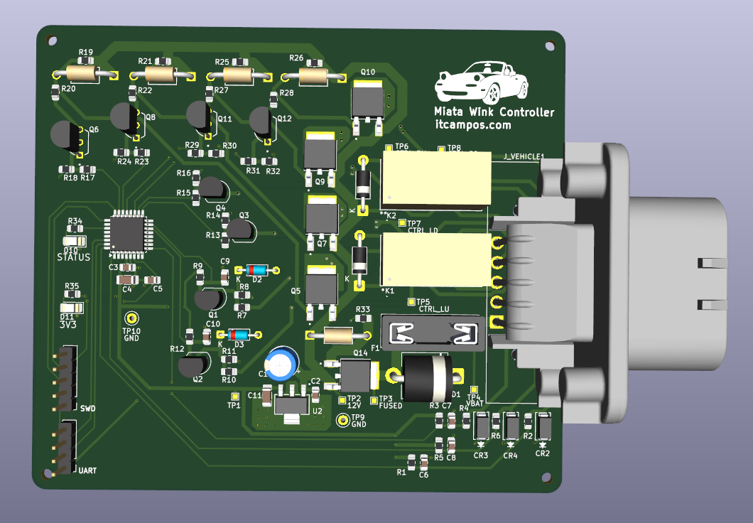
KiCad 3D model of the Rev B controller showing the STM32 section, relay-control hardware, automotive connector, protection circuitry, debug headers, and final component placement.
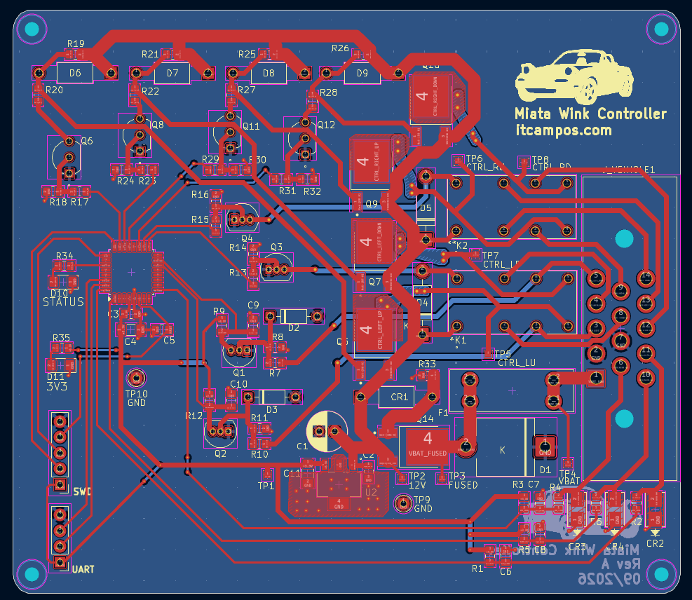
Routed KiCad PCB layout showing the STM32 control section, relay drivers, power distribution, protection components, test points, and vehicle interface.
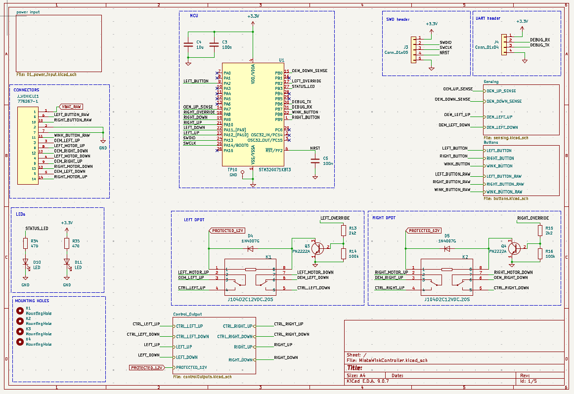
Top-level system schematic showing the STM32G071KBT3, vehicle connector, SWD and UART interfaces, status LEDs, relay stages, sensing circuits, and control outputs.
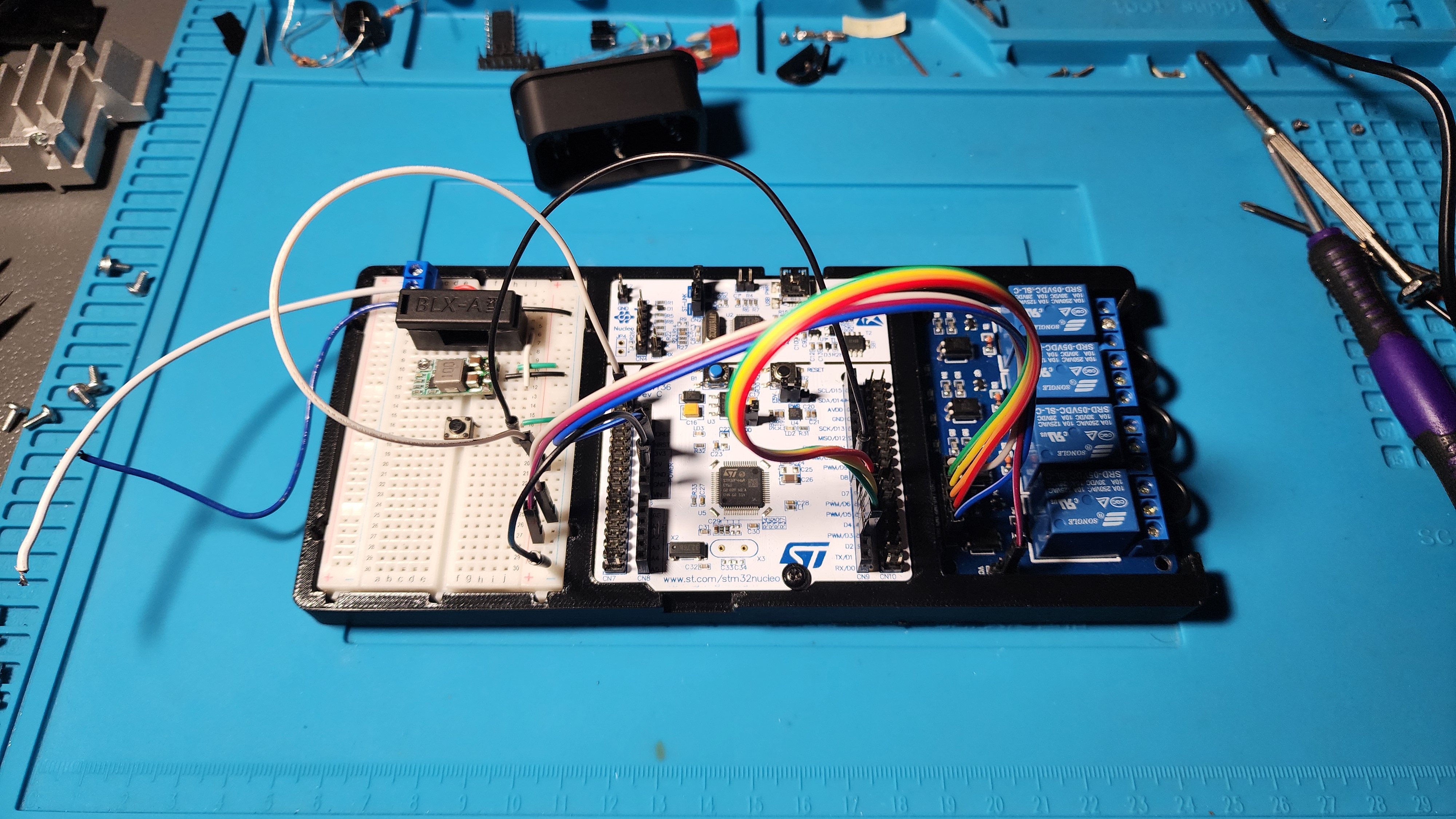
Early functional prototype using an STM32F446RE Nucleo, four-channel relay module, and breadboarded support circuitry to validate headlight-control logic before moving to the custom PCB.
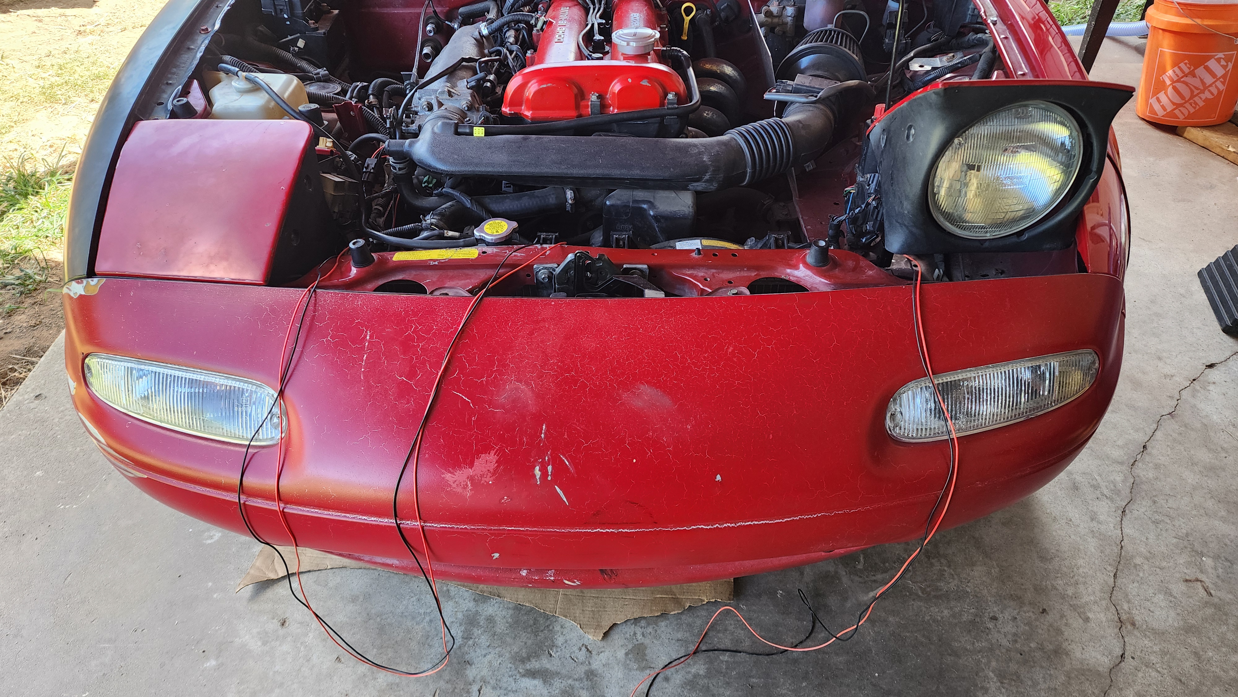
Functional testing on the Mazda Miata using the prototype controller to verify independent headlight movement, relay sequencing, timing behavior, and real vehicle wiring before finalizing the dedicated PCB design.